Introduction to Electronics
Electron
Emission of electron
- If electorodes (cathode and anode ) are set in vacuum and connected to high voltage of power supply, electrons are emitted from the cathode (Negative side of circuit) and flow to the anode (Positive side of circuit).
- A hot surface emits electrons. This emission of electrons from a hot surface is called thermionic emission .
- The flowing of electrons from cathode to anode is called the cathode ray .
Characteristics of an electron
- An electron has a smaller mass than a proton or a neutron
- Cathode rays travel in straight lines.
- Electrons are negatively charged so that they attract to anode (positive side).
- A magnetic field and an electric field change the direction of cathode rays
- The flow of electrons is opposite to the direction of current in the circuit. The current is called convenitional current.
Structure of Cathode Ray Oscilloscope (C.R.O.)
The diagram below shows the structure of a C.R.O.
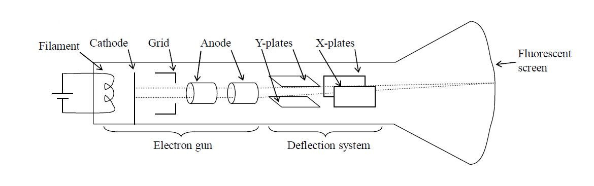
- A C.R.O. consists of three main parts. They are electron gun, deflection system and fluorenscent screen.
- An electron gun sends electrons through the vacuum to a fluorescent screen and a light spot appears on the screen.
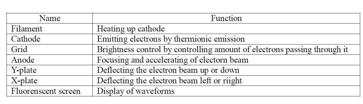
Each part has its function as shown in the table below.
Measuring voltage
- The C.R.O. can be used as a voltmete
- It can measure both A.C. and D.C. voltages.
- It measures the peak voltage of A.C. input signal.
- Y-gain setting indicates the voltage applied in order to deflect the beam by 1cm on the screen in the vertical direction. If Y-gain setting is 5V/cm, it means that 1cm of the height on the screen shows 5V of input signal.
Example 1
The diagram shows the screen of C.R.O. Y-gain setting is 3V/cm. What is the peak voltage applied to the Y-input of the C.R.O.?
Solution
Y-gain 3V/cm: 3V → 1cm
Peak voltage: x V → 3cm
Answer: x = 3×3 = 9V
Example 2
The gain control of a C.R.O. is set at 2V/cm. If the horizontal trace is deflected upwards by 5cm, what is the unkown voltage applied to the Y-input of the C.R.O.?
Solution
Y-gain 2V/cm: 2V → 1cm
Unkown voltage: x V → 5cm
Answer: x = 2×5 = 10 V
Measuring short time interval
- C.R.O. can be used to measure short time interval.
- Time base setting indicates the time needed for the light spot to sweep through 1cm on the screen in the horizontal direction.
- If the time base setting is 5ms/cm, it means that 1cm of the horizontal length on the screen shows 5ms (millisecond).
Example 3
The diagram shows the screen of C.R.O. The time base is set to 5ms/cm.
(a) What is the period of the input a.c. signal?
(b) What is the frequency of the input a.c. signal?
Solutions
(a)
Time base 5ms/cm: 5ms → 1cm
x ms → 4cm
Answer: Period: x = 5×4 = 20ms
(b)
Given that
T = 20ms = 0.020s
f = ?
Answer: